H) Fixing Imported Geometry Errors Efficiently
Working with imported models can be tricky, especially when they contain geometric or topological issues. Fixing these errors early is key to keeping your SOLIDWORKS environment running smoothly.
For in-depth workflows, refer to the SolidPractices guide “Working with Imported 3D Data” (available to subscription customers on my.solidworks.com). Below are some essential best practices to improve performance when dealing with imported geometry.
1) Resolve All Topological Errors First
Topological errors—such as gaps, missing faces, or mismatched edges—can severely degrade model and drawing performance. Models with unresolved topology may cause issues such as:
Larger file sizes
Longer open, save, and update times
Poor drawing and print quality
Slow export performance to PDF, DWG, or DXF
Eliminating these issues early ensures stable, high-quality results throughout your design workflow.
2) Run Import Diagnostics Before Adding New Features
When a file is imported into SOLIDWORKS, it’s read as a collection of surfaces and solids made up of faces, edges, and vertices.
Before adding any new features, use Import Diagnostics to detect and repair geometry errors. Once additional features are added, the tool is no longer available for that model—so it’s best to diagnose and fix issues immediately after import.
3) Use the Check Tool to Locate Problem Features
For parts containing multiple imported features, it can be time-consuming to identify where the topological errors are. The Check tool quickly highlights which features contain problems, and it can be used at both part and assembly levels.
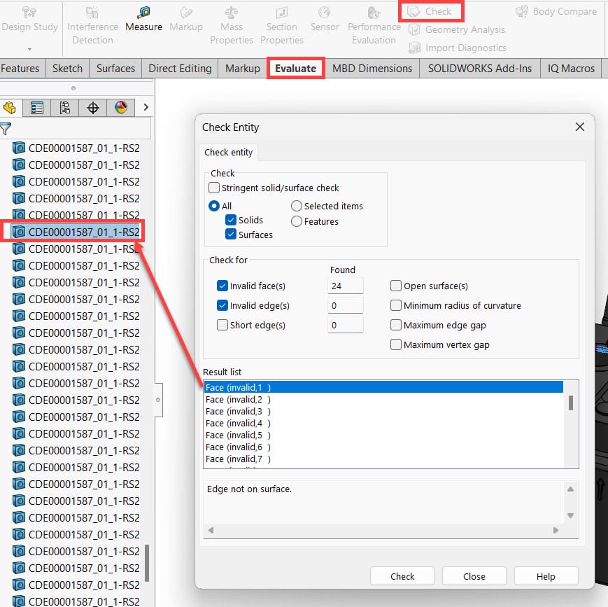
Figure 1
4) Apply the Invert Selection Tool
After identifying a faulty imported feature using the Check tool, close the tool, right-click in the graphics area, and select Invert Selection. This automatically selects everything except the problematic feature.
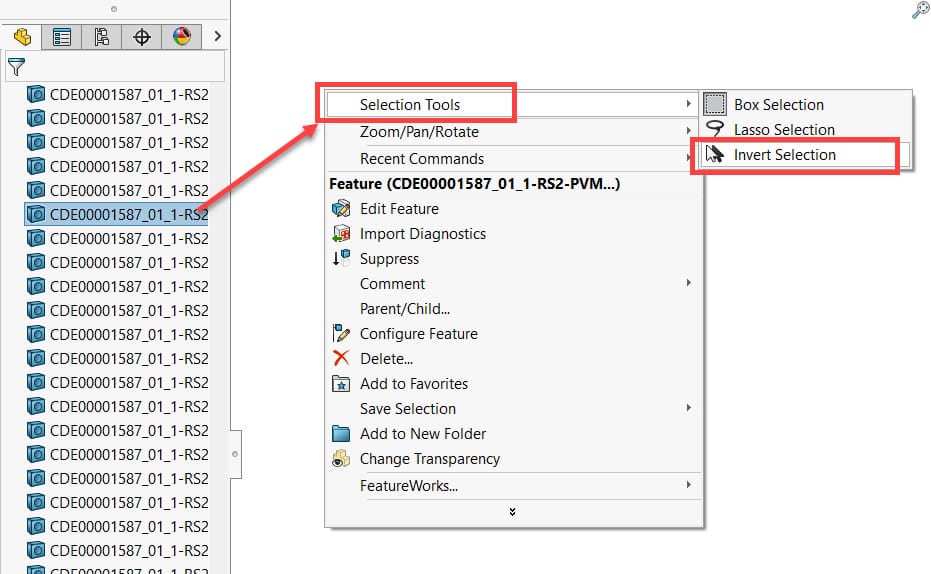
Figure 2
5) Suppress Other Features
Next, right-click again in the graphics area and choose Suppress. This suppresses all imported bodies except the one containing the error, making it easier to focus on repairing that feature.
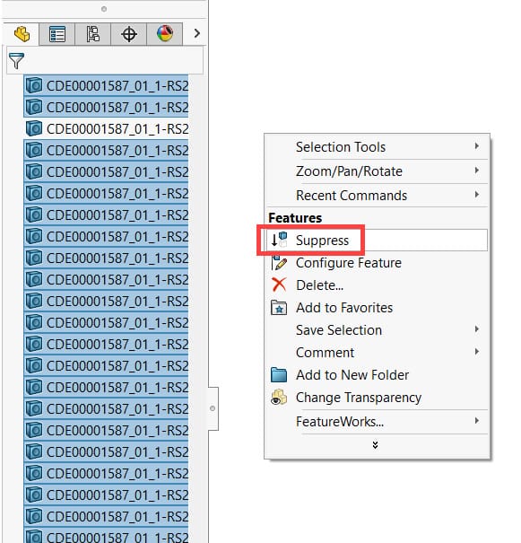
Figure 3
6) Run Import Diagnostics
With the simplified model active, run the Import Diagnostics tool. The process should complete within seconds, depending on the model size and complexity.
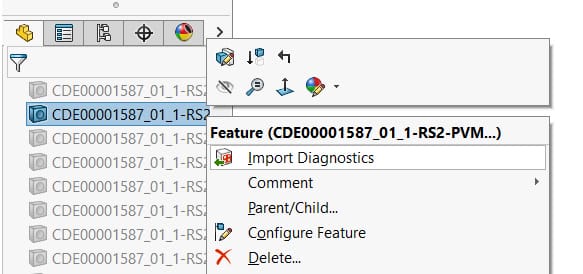
Figure 4
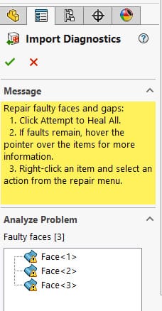
Figure 5
7) Repeat Until Fully Repaired
Once you’ve corrected the first issue, unsuppress the rest of the model and repeat the process until all imported features are free from topological errors.
You can refer to the Working with Imported 3D Data guide, or apply techniques learned in the Surface Modeling or Mold Design Using SOLIDWORKS courses to refine the repair process.
I) Using Part-Level Configurations Efficiently
Configurations are a powerful tool—but their use should align with your company’s data management and numbering strategy.
For many organizations, part numbers are tied to form, fit, and function. In such cases, it’s better to keep each variant as a separate file and use configurations only to create simplified or detailed representations for drawings or assemblies.
If your company does allow part configurations for design variations, ensure your team is trained in using them effectively. Helpful resources include:
Configuration and Display States lessons on my.solidworks.com
The SOLIDWORKS Essentials training course
Below are several useful tools and methods for troubleshooting within SOLIDWORKS:
1) Retain Configuration Data Used in Assemblies or Drawings
When body data is missing, SOLIDWORKS must rebuild the part every time it’s opened, which triggers updates in related assemblies and drawings.
Although saving all configuration data increases file size slightly, the performance gains outweigh the cost.
To ensure data is retained:
Disable the Purge cached configuration data option under System Options > Performance.
Confirm that all configurations used in assemblies or drawings display a checkmark beside their name.
To save body data for all configurations, press Ctrl + Shift + Q to rebuild them simultaneously.
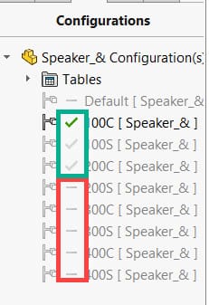
Figure 4: Configurations with checkmarks indicate cached body data
2) Avoid Multiple Dimension Drivers
Dimensions in SOLIDWORKS can be controlled by several different systems, such as:
Equations within SOLIDWORKS
Excel® design tables
Custom property equations
External references
Using multiple drivers simultaneously can cause repetitive rebuilds or, in worst cases, endless rebuild loops—greatly slowing down large assemblies and drawings. Always assign one clear driver per dimension.
3) Use Configuration Tables for Efficiency
From SOLIDWORKS 2022 onward, Configuration Tables offer a faster and lighter way to manage variations. At the part level, you can use them to:
Create and manage new configurations
Control feature suppression
Adjust dimensions
Define custom properties
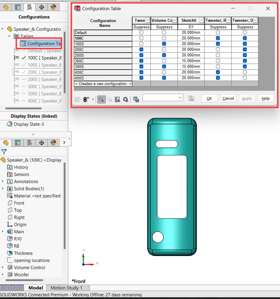
Figure 5: Configuration Tables simplify design management while improving performance compared to older Excel-based design tables.
This concludes Part 3 of our Best Practices for Modelling in the Part Environment series.
Together, these modules provide a strong foundation for creating cleaner, faster, and more reliable SOLIDWORKS part models.