Just like sketches, there isn’t necessarily a “good” or “bad” way to model parts in SOLIDWORKS. That said, the following best practices can help you work more efficiently and maintain cleaner, more reliable models.
A) Structure the FeatureManager for Maximum Productivity
A well-organized FeatureManager design tree saves time when it comes to:
Understanding the design intent
Editing models
Configuring parts
Locating features and sketches
Selecting entities
SOLIDWORKS offers several options to help configure the FeatureManager at the part level:
1) Switch between Classic and Flat Tree Views
When editing, it’s often easier to see sketches in their historical locations within the tree rather than being nested inside features. This is especially useful when using tools like the Rollback Bar or Part Reviewer.
You can use the right-click context menu (Figure 1) or press CTRL + T to quickly toggle between Classic and Flat tree views.
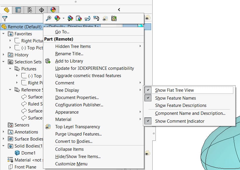
Figure 1: Or use “CTRL+T” as a shortcut that toggles between the Classic and Flat tree views
2) Name Features You Use Frequently
Renaming features makes them easier to find, especially when using the filter at the top of the tree. At a team level, you can further improve consistency by establishing naming conventions for important features. Document these standards and communicate them clearly to every designer.
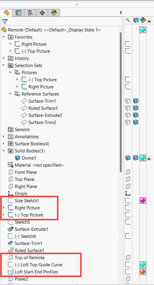
Figure 2: Named Features and Sketches
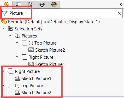
Figure 3: Using Filter
3) Add Frequently Accessed Entities to Favorites
Entities that you often edit or reference can be added to the Favorites folder. This makes them accessible instantly without having to scroll through the full design tree (Figure 4).
Figure 4
4) Use Comments for Notes and Shortcuts
Comments provide a convenient way to document important details directly in the model. They can also serve as shortcuts to access features, configurations, or sketches.
This is especially useful for leaving instructions or warnings for other users when the model is opened.
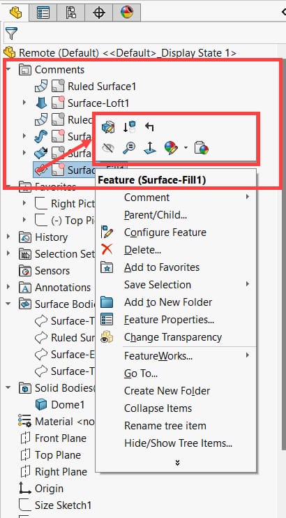
Figure 5
5) Use Selection Sets
Selection Sets let you save groups of entities for quick access later. This is very useful for bulk operations, such as showing or hiding a group of reference sketches or surface bodies (Figure 6).
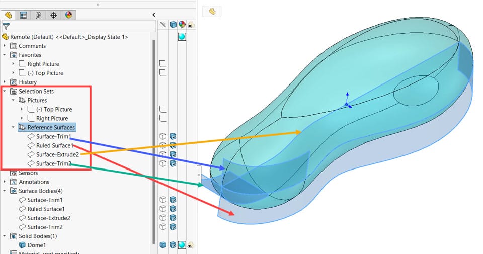
Figure 6: Confirmation corners next to the cursor for Sketch, Feature and Edit component.
B) Features vs. Bodies
Think of features as instructions, and bodies as the result of applying those instructions.
For example, a machinist’s process plan might include:
Start with a 2” thick plate
Cut an 8” × 12” piece
Punch center marks 1” from each corner
Drill and ream four ½” holes
These are equivalent to features in SOLIDWORKS. The actual cut plate with drilled holes is the body.
Features = Instructions (information)
Bodies = Geometry created by those instructions
This distinction explains why deleting a feature has a different effect compared to deleting a body.
C) Simple vs. Complex Features
In SOLIDWORKS, the same geometry can often be created in different ways. For efficiency, consider:
1) Modularity
Simple features make the FeatureManager longer but easier to edit when design intent changes.
Example: If rounds are created as sketch fillets, converting them to chamfers requires editing the sketch and replacing arcs with lines. If rounds are modeled as fillet features, you can simply suppress, delete, or convert them to chamfers.
This modular approach also gives greater flexibility for creating configurations.
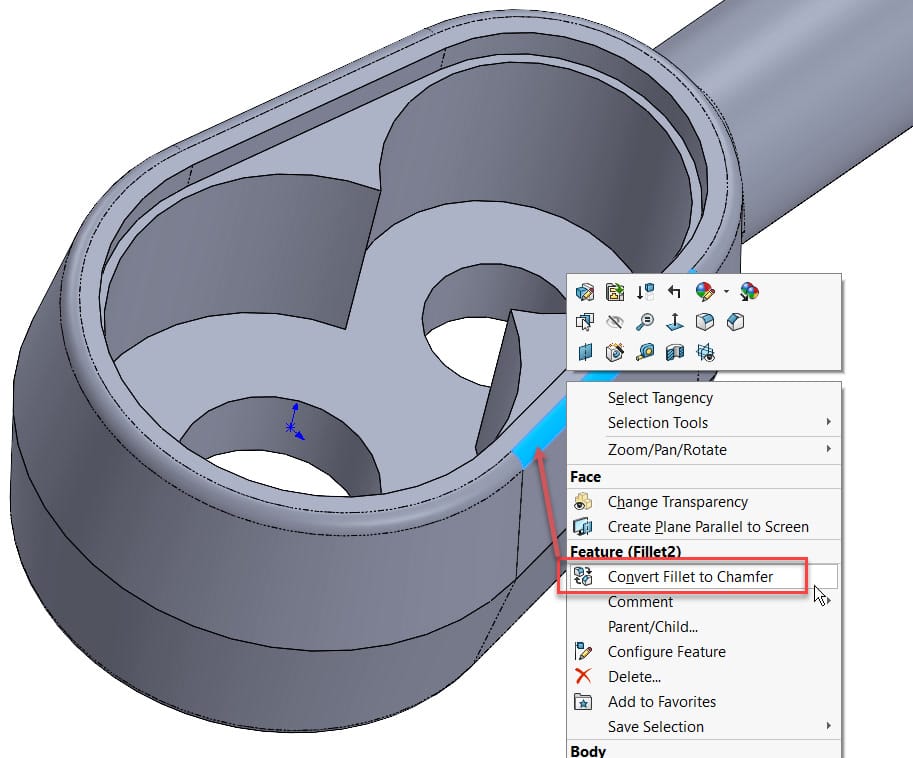
Figure 7
2) Robustness
Simple features are more resilient to changes. If a simple feature fails, it is easier to diagnose and fix compared to a large, complex feature.
For instance, a single complex Mutual Trim (Figure 8) can achieve the final geometry, but it is more prone to errors. Breaking it down into multiple trim features (Figure 9) makes troubleshooting far simpler.
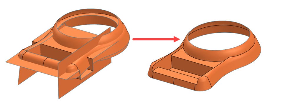
Figure 8
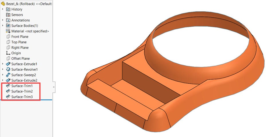
Figure 9
3) Rebuild Time
Complex features should be placed later in the tree.
In Figure 10, a complex pattern was created before other simple features. By moving it to the bottom (Figure 11), rebuild times decreased significantly:
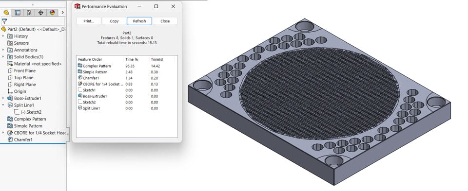
Figure 10
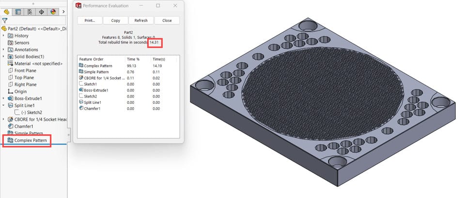
Figure 11
Feature | Rebuild Time (Before) | Rebuild Time (After) | Time Saving |
|---|---|---|---|
Complex Pattern | 14.42 | 14.19 | 1.6% |
Simple Pattern | 0.38 | 0.11 | 71.1% |
Counterbore Holes | 0.13 | 0.02 | 84.6% |
Chamfer | 0.20 | 0.00 | 100% |
Overall | 15.13 | 14.31 | 5.42% |
D) Hole Wizard vs. Cut-Extrude Features
Whenever possible, use Hole Wizard instead of Cut-Extrude for holes. Benefits include:
Quick changes to hole type and parameters
Standardized geometry
Built-in sketch pattern support
Compatible with Pattern Driven Component Pattern
Richer parametric dimensions and annotations for drawings
Simple workflow—just define hole positions
E) Patterns
Patterns are powerful tools for efficiency. Beyond duplicating features or bodies, they can also simplify geometry creation:
1) Up to Reference Option
Eliminates complex equations for spacing. Useful for resizing parts while keeping equal spacing between features (Figure 12).
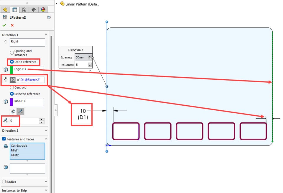
Figure 12
2) Vary Sketch Option
Copies a feature while adjusting dimensions automatically. Equivalent to creating multiple features with slightly different values (Figure 13).
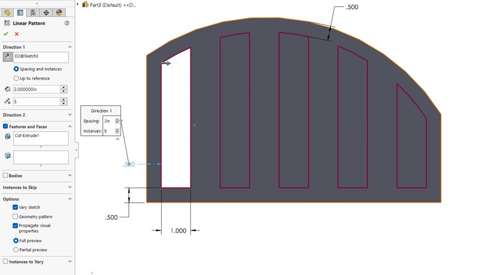
Figure 13
3) Instances to Vary Option
Provides full flexibility by allowing incremental spacing, incremental dimensions, or individual edits per instance (Figure 14).
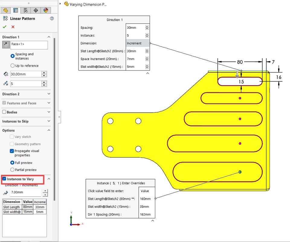
Figure 14
This is Part 1 of 3 in our Best Practices for Part Modelling series. Check back soon for the next module.