If you’ve spent some time drafting in DraftSight, you’ve likely come across the Chamfer command — a simple yet powerful feature often found right below the Fillet tool on the ribbon. It might seem subtle at first glance, but once you understand how chamfering works, it quickly becomes a go-to feature for refining corners and improving design precision.
So, what exactly does a chamfer do? How is it different from a fillet? And why should you use it in your drawings? Let’s explore.

What Is a Chamfer?
A chamfer is a beveled or angled edge that replaces a sharp corner with a straight, slanted line connecting two edges. Unlike a fillet, which creates a rounded transition, a chamfer keeps the geometry linear and clean.
In other words, while fillets soften corners with curves, chamfers create crisp, angled connections. The result is a chamfered edge that’s both visually neat and structurally purposeful.
In DraftSight, chamfering is commonly used to:
Eliminate sharp corners that might cause stress or damage
Indicate part fitment or alignment in mechanical drawings
Improve clarity and readability in architectural layouts
Chamfering is not just about appearance — it’s about precision and function.
Why Use Chamfered Edges in Design
Chamfers play an important role in both design and manufacturing. Here’s why professionals often prefer using them:
Improved safety: Chamfered edges reduce the risk of sharp corners.
Better fitment: Helps define where parts meet or align.
Easier production: Simplifies machining, printing, or assembly.
Enhanced aesthetics: Adds a clean, technical finish to drawings.
Using chamfers strategically can make your designs more readable and give them a polished, professional look.
Chamfer vs. Fillet — What’s the Difference?
It’s easy to confuse fillets and chamfers since both modify corners, but they serve different purposes:
Feature | Chamber | Filet |
|---|---|---|
Shape | Straight angled edge | Rounded Edge |
Purpose | Structural precision, sharp definition | Smooth transitions, flow |
Typical Use | Mechanical parts, architectural edges | Ergonomic or fluid designs |
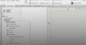
How to Create a Chamfer in DraftSight
Using the Chamfer tool in DraftSight is quick and flexible. Here’s how:
Activate the Chamfer command from the ribbon or type
CHAMFERin the command line.Choose your method:
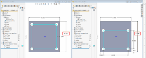
Distance – Set two distances from the corner edges.
Angle – Define one distance and an angle for the beveled edge.
Select the two lines that form the corner.
Confirm whether to trim or retain the original lines.
DraftSight will automatically apply the chamfer at the defined measurements.
Tip: If you’re working with a polyline, you may need to explode it first to chamfer individual corners. After editing, you can join the lines back together.
Best Practices for Chamfering
To get consistent and professional results when using chamfers:
Maintain uniform dimensions for chamfers throughout your design unless variation is intentional.
Double-check your units (millimeters, inches, etc.) to avoid uneven or oversized edges.
Balance chamfers and fillets thoughtfully — mixing both can enhance visual interest if applied purposefully.
Preview changes before finalizing, especially on complex geometry.
Consistent use of chamfers adds both function and refinement to your DraftSight projects. See more here.