Efficient SOLIDWORKS Modelling
It’s not entirely accurate to say there’s a “right” or “wrong” way to use sketches in SOLIDWORKS. The best approach depends on the type of product, workflow, and team practices in place. That’s why SOLIDWORKS provides such flexibility in how sketches can be created and applied.
Typical Use Cases for Sketches
While it’s impossible to cover every scenario, sketches in parts or assemblies are essential building blocks. Both 2D and 3D sketches can be used for:
Establishing design intent
Defining 3D features
Serving as reference geometry
Converting 2D DWG drawings to 3D SLDPRT files
Adding mates in assemblies
Providing references for detailing drawings
How Sketches Are Solved
When you create a sketch, SOLIDWORKS generates a system of equations based on every entity, relation, and dimension present. The software solves them simultaneously. Each additional element increases the complexity of these equations—often exponentially. That’s why even a small increase in sketch size can significantly impact performance.
2D versus 3D Sketches
Although 2D and 3D sketches appear to share the same tools (such as the line icon), they rely on different solving engines internally.
A 2D sketch handles two translational axes and one rotational axis.
A 3D sketch handles three translational axes and three rotational axes, dramatically increasing the number of variables.
Adding that extra degree of freedom makes the solving matrix far more complex, which is why, from a performance perspective, 2D sketches should be used whenever possible.
11 Simple Rules for Efficient Sketching
When working in teams, efficiency depends on three main factors:
Clarity
Modularity
Fast editing (including changes to design intent)
With these in mind, here are 11 best practices to follow when creating sketches for defining design intent or building 3D features.
1) Use simple sketches
As explained earlier, more sketch elements mean more solving time. Keep sketches simple to improve performance and enjoy benefits such as:
Easier for others to understand
Promotes modular design
Easier to document and troubleshoot
Minimizes errors
Faster to edit and configure
2) Make use of the origin and major planes
The origin and the three major planes are valuable reference geometry. Best practices include:
Sketch on major planes to reduce dependency chains (parent-child relationships).
Use symmetry with respect to the origin or planes.
In skeleton sketch workflows, referencing everything to the origin allows assemblies to be created without mates, since all components are fixed to the assembly origin.
3) Fully define sketches
Under-defined sketches are risky. They can lead to uncontrolled changes when references are edited. Worse, they make it difficult for reviewers to validate whether the intended design intent was followed.
Use the minimum relations and dimensions necessary to fully define a sketch. Adding excessive relations may not cause warnings, but it increases complexity, slows solving, and makes troubleshooting harder.
In the FeatureManager:
Under-defined sketches show as
(-) Sketch1.Over-defined sketches show as
(+) Sketch2.
4) Order of operations
When sketching, follow this sequence:
Create geometry.
Apply symmetry using Mirror Entities (saves time and auto-applies relations).
Add other relations as needed.
5) Finish by adding dimensions to fully define the sketch
Start dimensioning with the smallest values first to avoid geometry overlaps during edits.
Take advantage of inferencing lines while sketching—SOLIDWORKS can automatically add relations as you go.
For example, in Figure 1, a line starts from the left side of the circle. As the cursor moves over the circle, dotted inferencing lines appear, allowing you to apply one of these relations to the line and its endpoint automatically:
- Tangent line – circle
- Tangent line – circle and coincident line endpoint – circle
- Coincident line – center of circle
- Coincident line – center of circle and coincident line endpoint – center of circle
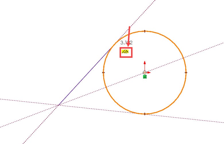
Figure 1
6) Minimize driving dimensions to match design intent
Where possible, rely on relations instead of extra dimensions.
Example: In Figure 2, using the equidistant relation allows you a Hole Wizard sketch by one dimension. In this case, you do not dimension the distance between instances of the hole because that is not your concern. Your design intent is to ensure only that the holes have equal spacing.
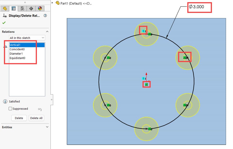
Figure 2
7) Drag under-defined entities to test
A fully defined sketch leaves no ambiguity. If you’re unsure what’s missing, drag under-defined entities to see how the geometry shifts. This helps identify which relations or dimensions are required.
8) Fix errors as they occur
Errors can arise from both your own actions (e.g., adding conflicting relations) or from external changes made by others (e.g., editing references in assemblies).
Always fix sketch errors immediately:
Errors slow down solving.
Geometry may not update correctly.
Downstream sketches and features may also break.
Tools to assist:
Check Sketch for Feature Usage – to validate sketch geometry for dependent features.
SketchXpert – to identify and resolve over-definition issues.
Select all sketch entities bordering the shaded region with one click to instantly perform actions like:
- Move entities in bulk with no distortion by dragging the shaded area.
- Run the Offset Entities – Figure 3(a)
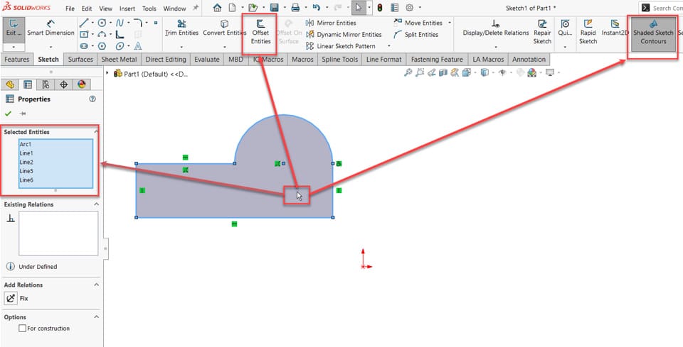
Figure 3(a): One click to select all sketch entities forming the contour
- Troubleshoot open contours
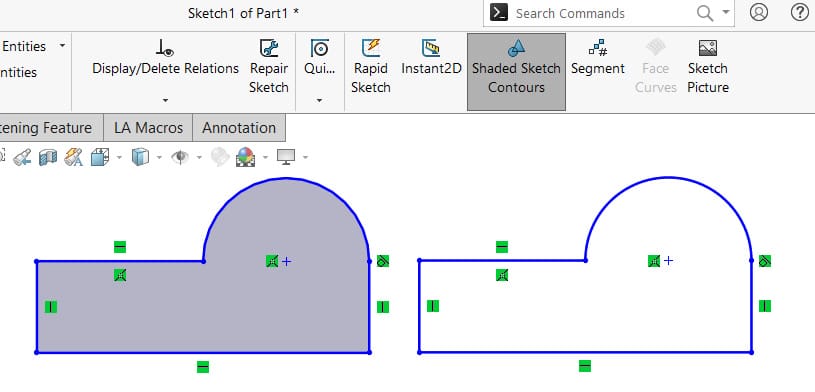
Figure 3(b)
10) Use Replace Entity to preserve references
Instead of deleting and redrawing sketch entities (which breaks references), use Replace Entity. The new entity inherits references from the old one, saving time and avoiding rework. – Figure 4
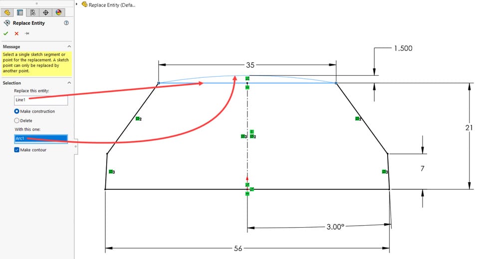
Figure 4
11) Select the largest reference entity when using tools
When referencing geometry with tools like Convert, Offset, Silhouette, or Intersection Curve, choose entities in this order:
Body
Face
Edge
Referencing higher-level geometry creates more robust sketches. Even if individual edges change later, sketches remain stable when referencing faces or bodies. – Figure 5(a) and Figure 5(b)
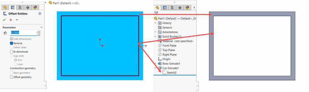
Figure 5(a) – Face selected for the Offset Entities tool.
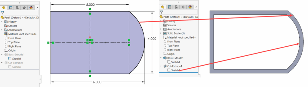
Figure 5(b) – The Cut-Extrude updates properly when the referenced face changes shape.