Just like sketches, there isn’t necessarily a “good” or “bad” way to model parts in SOLIDWORKS. That said, the following best practices can help you work more efficiently and maintain cleaner, more reliable models.
F) Working Efficiently with Downloaded Files
When downloading supplier files—especially fasteners or standard hardware—always take a few minutes to clean them up before adding them to your design library. This helps reduce file size, improve rebuild times, and enhance overall system performance.
1) Remove or Suppress Unnecessary Cosmetic Features
Downloaded parts often include detailed cosmetic threads, knurls, or surface markings. If your design doesn’t require these details for visual or functional purposes, suppress or delete them.
Every additional surface and edge increases computation and graphics load, especially when assemblies contain hundreds or thousands of identical components. A simplified model will display and rebuild far faster while looking nearly identical in context.
(Example: Consider the difference in performance between an assembly with 1000 screws with detailed threads versus smooth cylindrical shanks.)
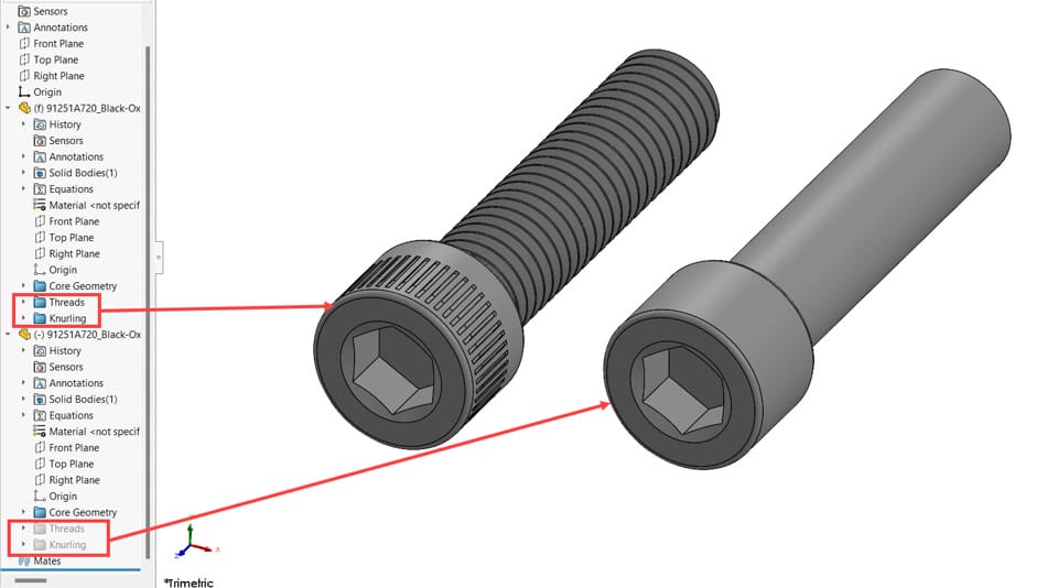
Figure 1
2) Standardize Image Quality Settings
Each model inherits the image quality settings defined by its creator. High image quality improves visual smoothness but also increases file size and slows rendering and rotation performance.
Before saving supplier files, adjust the image quality slider in Document Properties > Image Quality according to your company’s standard settings.
You’ll often notice a major reduction in graphics triangles—with minimal change to appearance. In one test case, a fastener’s graphics complexity dropped by over 95% after optimization.
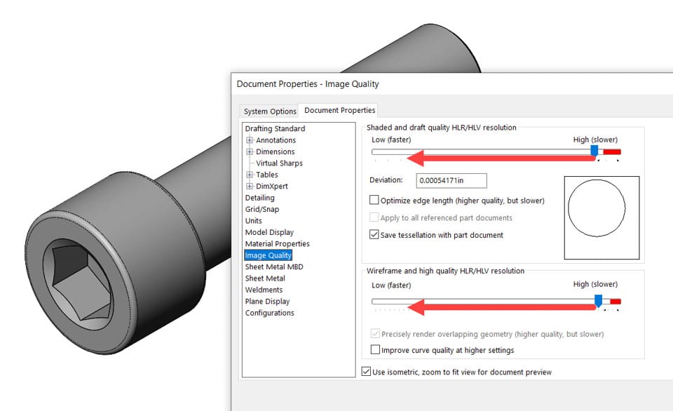
Figure 2
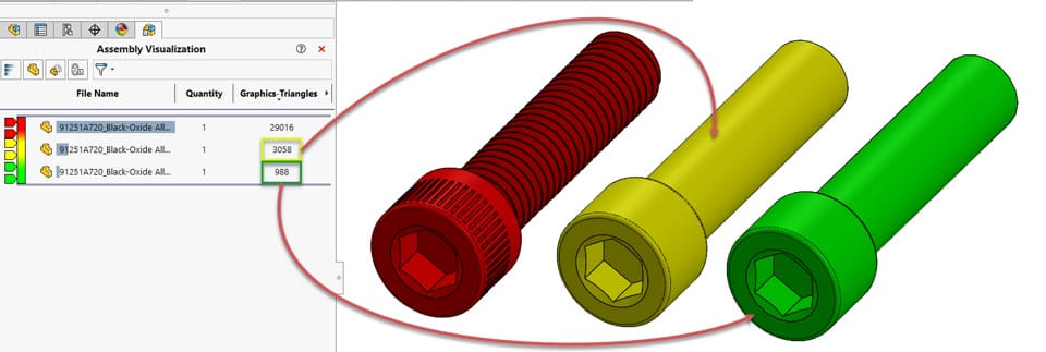
Figure 3
3) Remove Unnecessary Equations
Some vendor models include embedded equations for parametric sizing or automation. Since you’re typically downloading one version of a component, these equations serve no purpose and can slow down rebuild operations.
Delete them to prevent unnecessary evaluations and streamline performance—especially in large assemblies.
G) Tools for Troubleshooting Models
During design revisions, features may occasionally fail or display warnings in the FeatureManager. Training users to diagnose and resolve these issues early ensures cleaner, error-free models before they’re checked into the PDM vault.
Below are several useful tools and methods for troubleshooting within SOLIDWORKS:
1) Rebuild vs. Forced Rebuild
Rebuild (Ctrl + B): Rebuilds only features that have changed since the last save or rebuild. This is the default and most efficient approach.
Forced Rebuild (Ctrl + Q): Rebuilds every feature in the part or assembly, even if unchanged. Use this primarily for diagnostics, as it can take considerably longer.
2) Troubleshoot from the Top of the Tree
SOLIDWORKS models follow a chronological feature order. Errors in parent features often cascade down to dependent features.
Start fixing issues from the top of the tree—resolving parent errors first usually clears multiple downstream issues automatically.
You can switch to Flat Tree View to visualize features in true historical order for easier debugging.
3) Using the Rollback Bar
When repairing a model, move the Rollback Bar to the point where the first error occurs.
As you correct each issue, roll forward step by step to continue testing. This targeted approach helps avoid unnecessary rebuilds of the entire part.
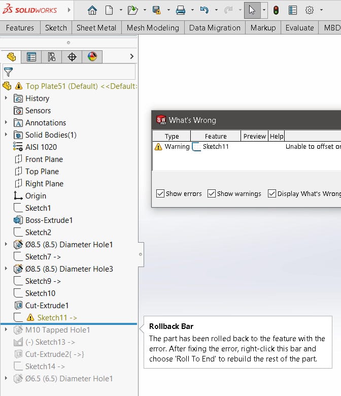
Figure 4
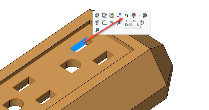
Figure 5
4) Quick Access to Errors and Warnings
Click on the part name in the FeatureManager to open a list of all current errors and warnings. Selecting an entry jumps directly to the affected feature—saving time when navigating large trees.
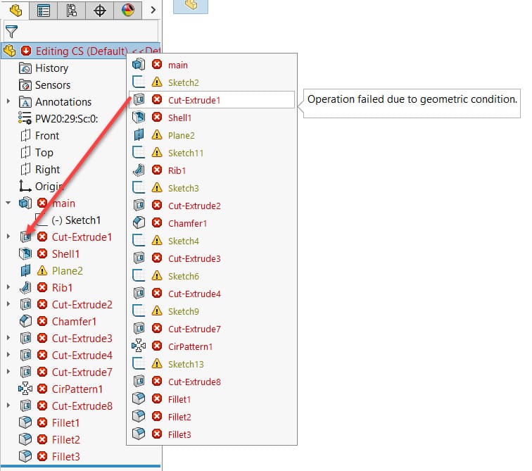
Figure 6
5) Display/Delete Relations in Sketches
To isolate sketch-level errors, use the Display/Delete Relations tool. This tool lists all constraints within the sketch, helping you locate and manage invalid or dangling relations efficiently.
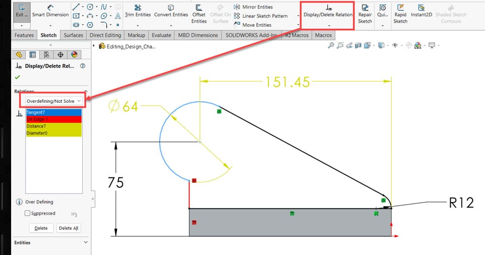
Figure 7
6) SketchXpert for Overdefined Sketches
When a sketch becomes overdefined, activate SketchXpert by clicking the Over Defined message on the status bar.
In the property manager, click Diagnose to explore alternative constraint combinations until a valid configuration is found.
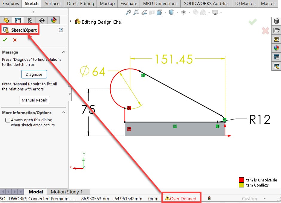
Figure 8
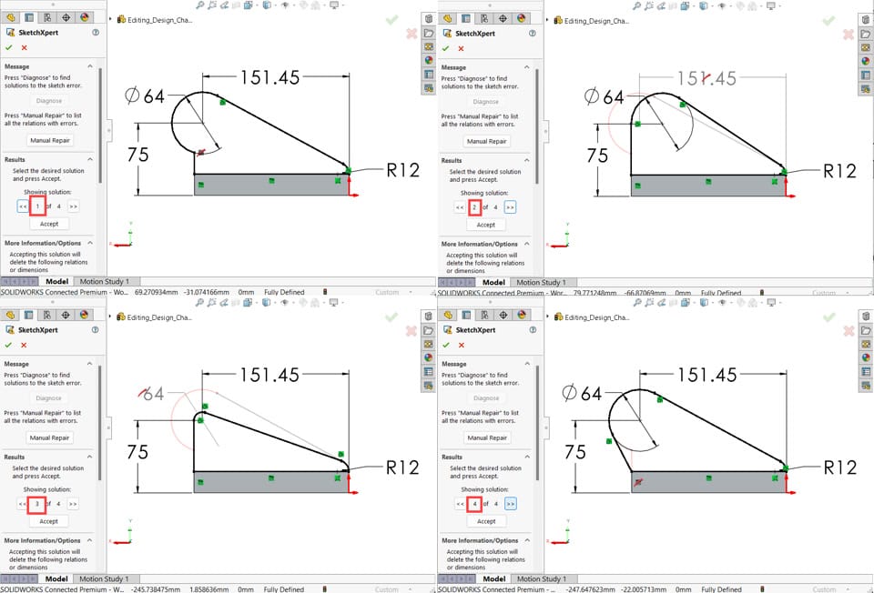
Figure 9
7) Reattaching Dangling Relations and Dimensions
If a sketch reference is broken, select the dangling entity to reveal a small red dot. Drag the dot to a new valid reference to reattach the relation or dimension—restoring sketch stability without recreating geometry.
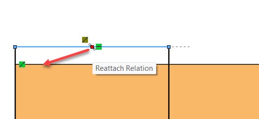
Figure 10
8) Using the Freeze Bar
For parts with long feature trees or slow rebuilds, the Freeze Bar can temporarily lock features above it to prevent rebuilds.
Frozen features display gray text and a small lock icon. This tool is best used selectively—only for sections of the model that are fully finalized.
Note that freezing all part features won’t necessarily make assemblies load faster, since parts generally don’t rebuild when opened in assemblies unless geometry data is outdated. Always unfreeze features file by file when updates are required.
This is Part 12of 3 in our Best Practices for Part Modelling series. Check back soon for the next module.