When engineers say they “design in SOLIDWORKS,” the truth is that the actual design work usually happens before the modelling even begins. That’s why it’s important to make a clear distinction: designing is about defining the concept, while modelling is about building the shape and details of that design in SOLIDWORKS.
For example, imagine you already have a complete 2D drawing of a part. The next step is to turn it into a 3D model using SOLIDWORKS. The software gives you multiple ways to build the same part, which is great for flexibility — but it can also create challenges when changes come later.
Here’s the catch: if your model was built with future changes in mind, making updates is fast and painless. If not, a simple revision could mean hours or even days of rework. That’s why efficient SOLIDWORKS users focus on Modelling for Change. This principle is known as Design Intent — the plan for how your model should react when the design evolves.
Capturing Design Intent in SOLIDWORKS
SOLIDWORKS offers many tools to help you build models that are easier to update. Some of the most effective techniques include:
- Sketch relations and dimensions to control geometry
- Start and end conditions when creating features
- Patterns and equations for consistent updates
- Mating schemes for assemblies
- Skeleton sketches (base part technique) for driving multiple components
- Envelope Publisher to reference external geometry
- Configurations to manage design variations
By using these methods, you create models that stay robust even when requirements change.
A Simple Example
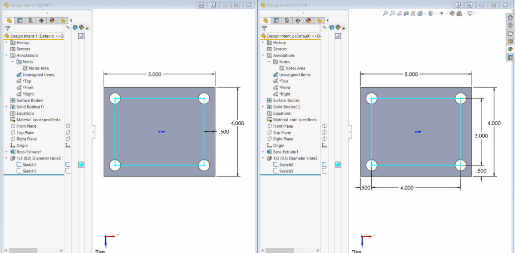
Take two parts that look identical at first glance. Both are based on the same initial design and even share the same feature tree in SOLIDWORKS. The difference lies in how they were modelled.
In the first part, hole positions were defined using an offset from the edges. No matter how the plate size changes, the holes always stay a fixed distance from the border.
In the second part, hole positions were tied to multiple dimensions — the overall width, height, and distances between holes.
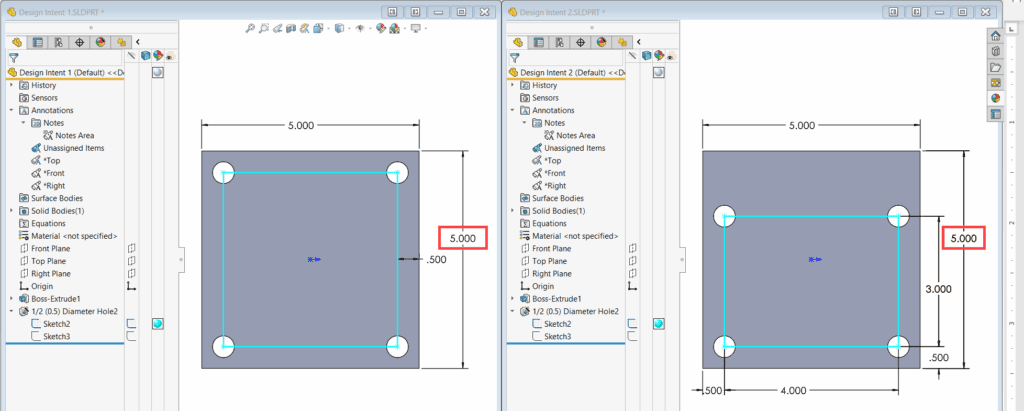
Now, if the plate height changes from 4” to 5”, the first part automatically adjusts while keeping the design intent. The second part, however, may no longer look right and needs extra editing.
This small difference in modelling approach can save hours during revisions.
Why This Matters for Teams
SOLIDWORKS offers many tools to help you build models that are easier to update. Some of the most effective techniques include:
- Sketch relations and dimensions to control geometry
- Start and end conditions when creating features
- Patterns and equations for consistent updates
- Mating schemes for assemblies
- Skeleton sketches (base part technique) for driving multiple components
- Envelope Publisher to reference external geometry
- Configurations to manage design variations
By using these methods, you create models that stay robust even when requirements change.
Final Thought:
In Malaysia and Singapore’s fast-moving manufacturing environment, efficiency is everything. Whether you’re an engineer building models or a manager overseeing teams, understanding and applying design intent in SOLIDWORKS can make the difference between days of rework and just a few clicks.