Detail drawings are where a design becomes buildable. While plans, elevations, and sections communicate the overall intent, a detail drawing focuses on a specific area and explains exactly how it should be assembled, connected, or installed.
If you have ever seen a contractor ask, “How does this join?” or “What is the fixing method here?”, that is the gap detail drawings are meant to solve.
What is a detail drawing?
A detail drawing is a close-up technical drawing that shows a component or junction at a larger scale. It captures information that is usually too small to communicate clearly in general drawings.
A detail drawing may include:
precise dimensions and notes
material callouts
fixing methods and connection details
tolerances or clearances, when relevant
section views to show internal relationships
The purpose is to remove uncertainty and make the build process easier to follow.
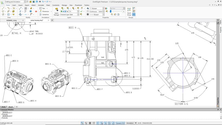
Detail drawing example
Think of a detail drawing like zooming in on a critical part of the design.
A building plan might show the locations of walls and windows, but a detail drawing can show how the window frame connects to the wall, how waterproofing is applied, and where the fasteners are placed.
In mechanical or product design, a detail drawing might focus on a housing, bracket, or interface between parts, including dimensions and features that must align correctly during assembly.
Where detail drawings are used
Detail drawings are common in both construction and engineering because they prevent guessing. When teams can see exactly how elements should come together, there are fewer site questions and fewer reworks.
Detail drawings are usually produced once the overall design direction is set and the project is moving into coordination and documentation.
Construction detail drawings
Construction detail drawings support the practical “how to build it” part of a project. They often zoom in on interior or exterior building elements such as:
wall build-ups and insulation layers
door and window installation details
floor and roof junctions
waterproofing, flashing, and edge conditions
cabinetry, finishes, and joinery details
A good construction detail drawing is easy to read and hard to misinterpret. Clear notes, correct scale, and clean dimensioning matter because site teams rely on these drawings to execute work accurately.
Detail drawings are usually produced once the overall design direction is set and the project is moving into coordination and documentation.
Engineering detail drawings
Engineering detail drawings are typically more technical and may include functional requirements that support safety and performance. They often show:
component geometry and critical dimensions
specifications for materials and finishes
tolerances and fit where required
connection methods for structural and mechanical elements
For example, a steel member detail might include sizes and connection information needed to fabricate and install it correctly.
Digital tools that help detail drawings
If you create detail drawings often, DraftSight can help you work faster and keep drawings consistent:
layers for better organization
blocks and templates for reuse
tools for clean linework and annotation
Tips for accuracy and clarity in detail drawings
You have a few options based on what you need to do.
1) Use consistent labeling and notation
Consistency is one of the fastest ways to improve readability. Use the same naming format for parts, notes, and callouts across all drawings. Keep text styles and symbols aligned with your office standards.
A practical approach:
keep notes short and direct
avoid vague language like “fix as required”
label critical components clearly and consistently
2) Choose the right scale for the information
General drawings often use smaller scales, but detail drawings need a larger scale so connections and materials are readable.
Examples of common detail scales include 1:10 or 1:5, depending on what you need to communicate. The goal is simple: the detail must be readable at the intended print size.
3) Dimension only what the builder or fabricator needs
More dimensions do not always improve clarity. Too many dimensions can create clutter or cause conflicting values if revisions occur.
A better approach:
dimension critical sizes, clearances, and reference points
avoid repeating the same dimension in multiple places
ensure dimensions support how the element is built or measured onsite
4) Use layers and lineweight discipline
Layer structure helps readers separate key information quickly, especially when a detail includes multiple systems.
A good layer strategy:
separate structure, finishes, and services where possible
keep hidden or secondary elements lighter
make cut lines and key edges visually stronger
5) Add section views where needed
When a junction cannot be explained clearly in a single view, add a section or callout detail. Sections often communicate build-ups and internal relationships better than plan views alone.
6) Keep details tidy and easy to scan
Readability is not only about accuracy. It is also about how quickly someone can understand the detail.
Do a quick print check:
confirm text is readable at scale
verify that dimensions do not overlap
ensure hatches do not overwhelm the drawing
check that leaders and callouts point clearly to the correct items
Want a smoother workflow for CAD detail drawings?
DraftSight can support detail drawing production with tools for layers, annotation, templates, and dimensioning workflows.
Adapted from DraftSight Blog: “Detail Drawing: Techniques for Accuracy and Clarity”.